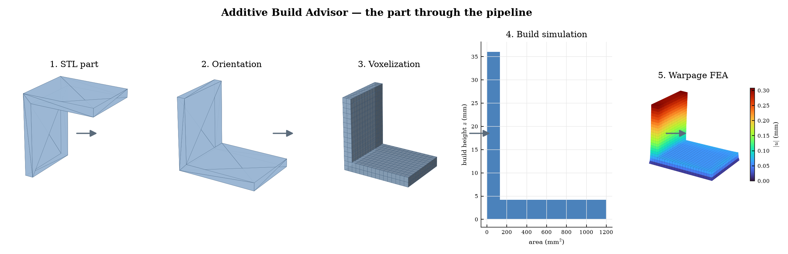
It takes a part geometry (STL), decides how to build it, simulates the build, runs a
finite-element distortion analysis, checks whether the part can actually be made and
measured, and emits one auditable record with an explicit release gate:
release_to_build, needs_engineering_review, or redesign_required.
The part through the pipeline
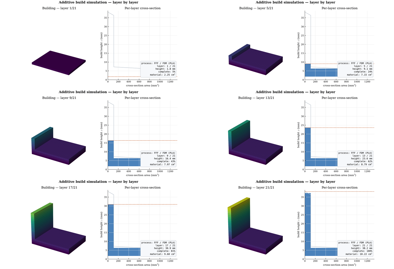
Build simulation (animated)
The part building up layer by layer on the plate, with a live metrics panel — the additive analog of a runtime process dashboard:
How it works
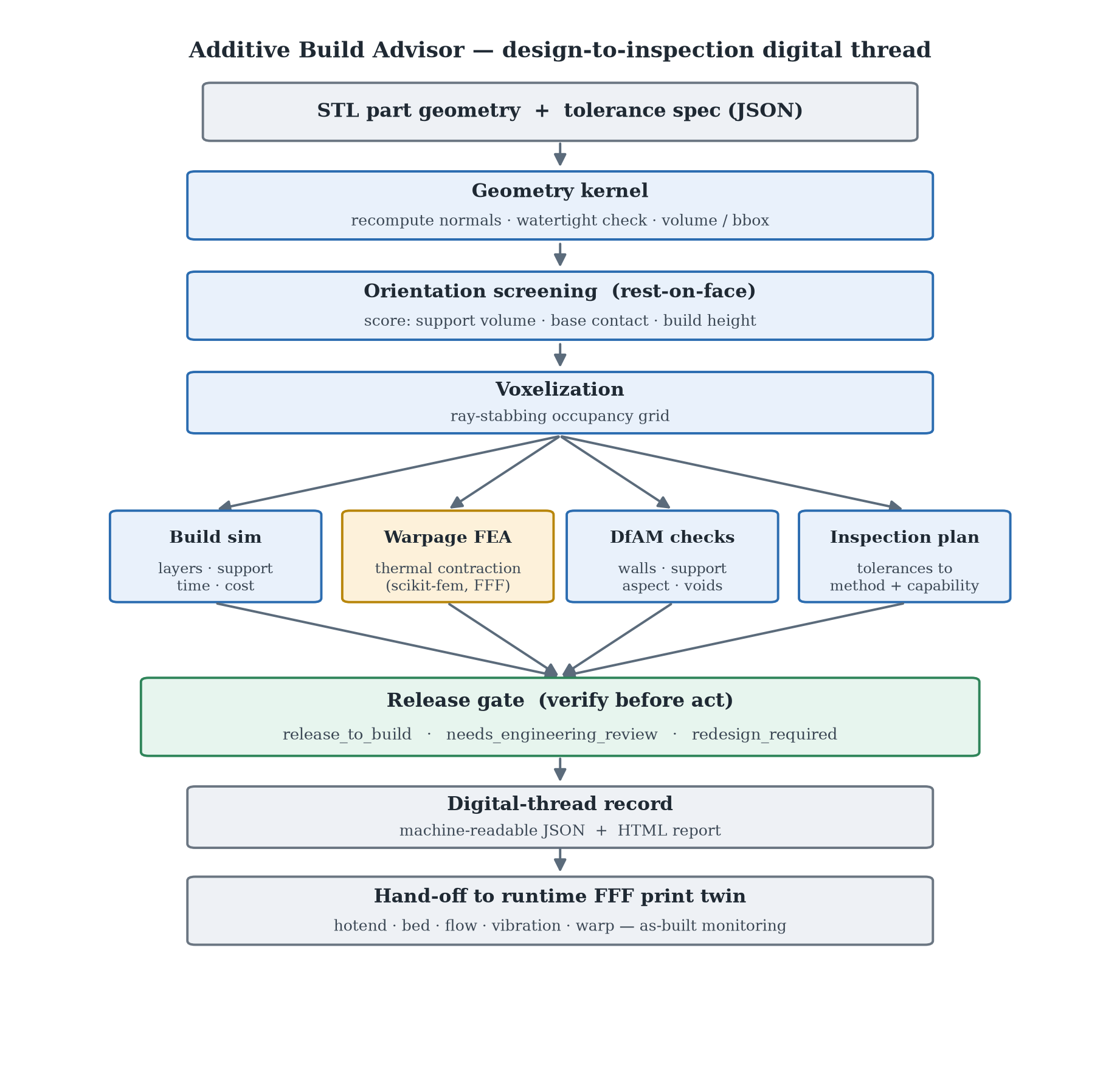
Geometry kernel
Parse the STL, recompute normals, verify watertightness; voxel volume cross-checked against the analytic mesh volume.
Orientation
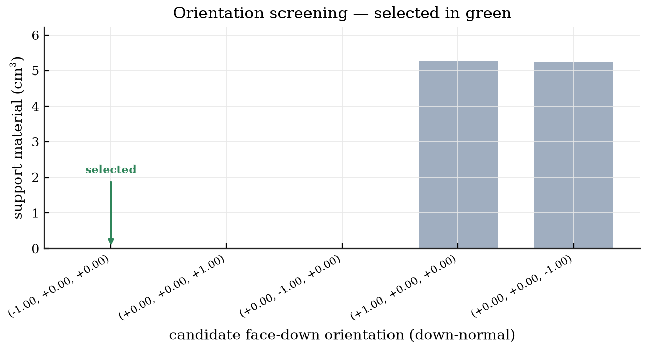
Rest-on-face candidates scored on real support volume, base contact, and build height.
Build simulation
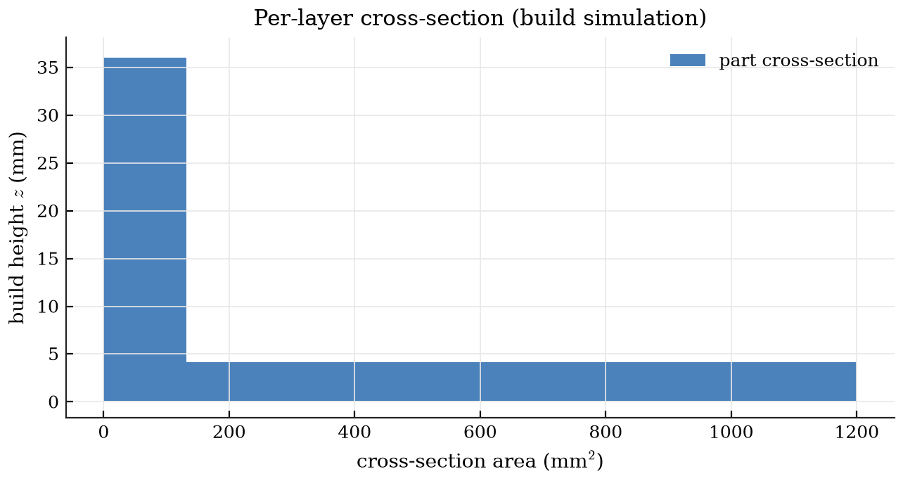
Voxelize by ray-stabbing; estimate layers, support, build time, and cost.
Warpage FEA
Thermal-contraction (eigenstrain) linear-elastic solve with scikit-fem; the corner-lift that warps FFF parts off the bed.
DfAM + inspection
Thin walls, support, aspect ratio, trapped voids; tolerances vs as-built capability.
Release gate
Release, review, or redesign — with reasons — then a machine-readable record.
Warpage FEA (thermal-contraction method)
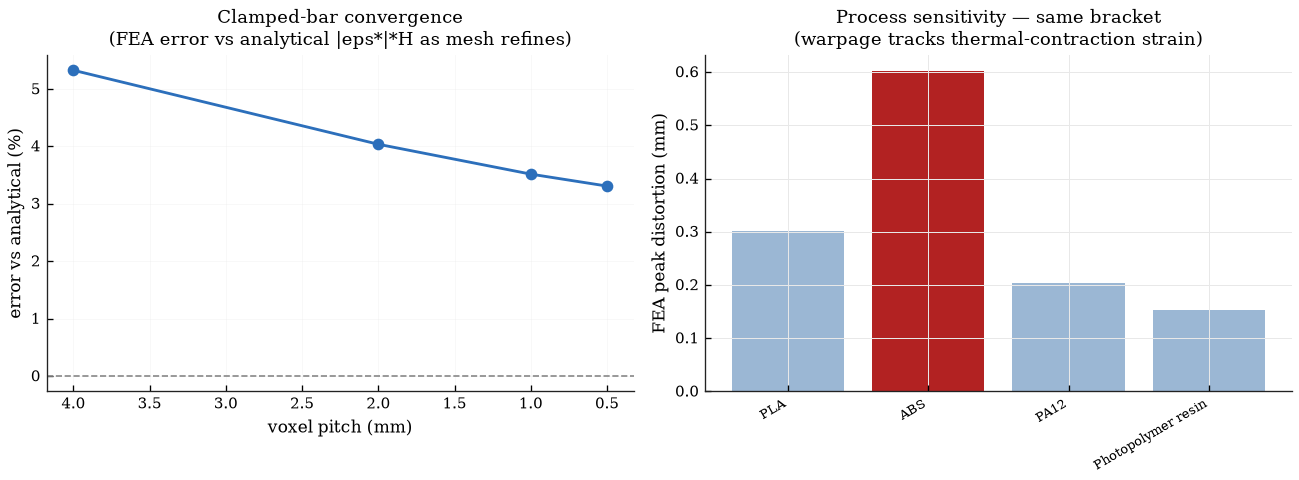
Warpage is predicted with a genuine finite-element solve, assembled and solved with
scikit-fem on a hexahedral mesh. Each element carries a thermal-contraction
eigenstrain (ε* ≈ −α·ΔT, the part shrinking as it
cools), the first layer is clamped to the bed (the bed-adhesion constraint), and the displacement field
is the predicted warpage — the corner-lift that curls FFF parts off the bed. It is a standard way to
screen build warpage without a full transient thermo-mechanical solve. The solver is validated against
the analytical clamped-bar solution, and the predicted distortion is linear in the contraction strain
and independent of Young's modulus — as linear elasticity requires for an eigenstrain-only load.
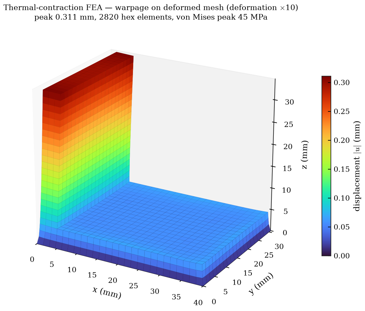
Honest scope: the model reports the on-bed warpage (part still bonded to the bed), not the spring-back after the part is peeled off; reproducing that needs a release step and a contraction strain calibrated to measured cooling.
Orientation & build simulation
Sample results
The example runner exercises all three gate outcomes (numbers from a real run):
| Part | Process | Build time | Cost | Warpage FEA | Gate |
|---|---|---|---|---|---|
| calibration_cube | FFF (PLA) | 0.71 h | $3.79 | 0.158 mm | release_to_build |
| gantry_bracket | FFF (PLA) | 0.80 h | $4.24 | 0.311 mm | needs_engineering_review |
| hollow_housing | SLA (resin) | 1.94 h | $17.16 | 0.102 mm | redesign_required |
| cantilever_benchmark | FFF (ABS) | 0.46 h | $2.93 | 0.143 mm | needs_engineering_review |
The bracket prints cleanly but carries a ±0.05 mm tolerance and a 3.2 µm finish that are below FFF as-built capability, so it is routed to engineering review to finish those features on the mill — the call the ES 51 lab makes. The last row is a long, flat ABS bar, the worst-case warp geometry.
Cross-process comparison
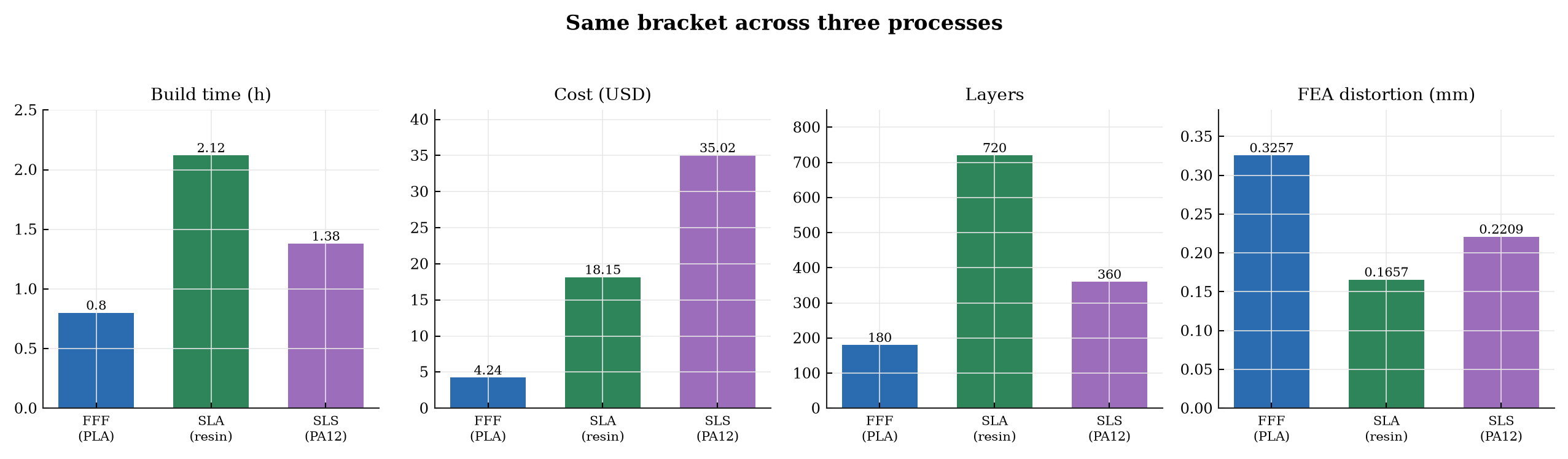
The build simulation, cost/time, DfAM, and warpage FEA run natively for every process. FFF is the home process; SLA and SLS are shown as a cross-process comparison. The same bracket through three additive processes:
Where the thread continues — runtime FFF print twin
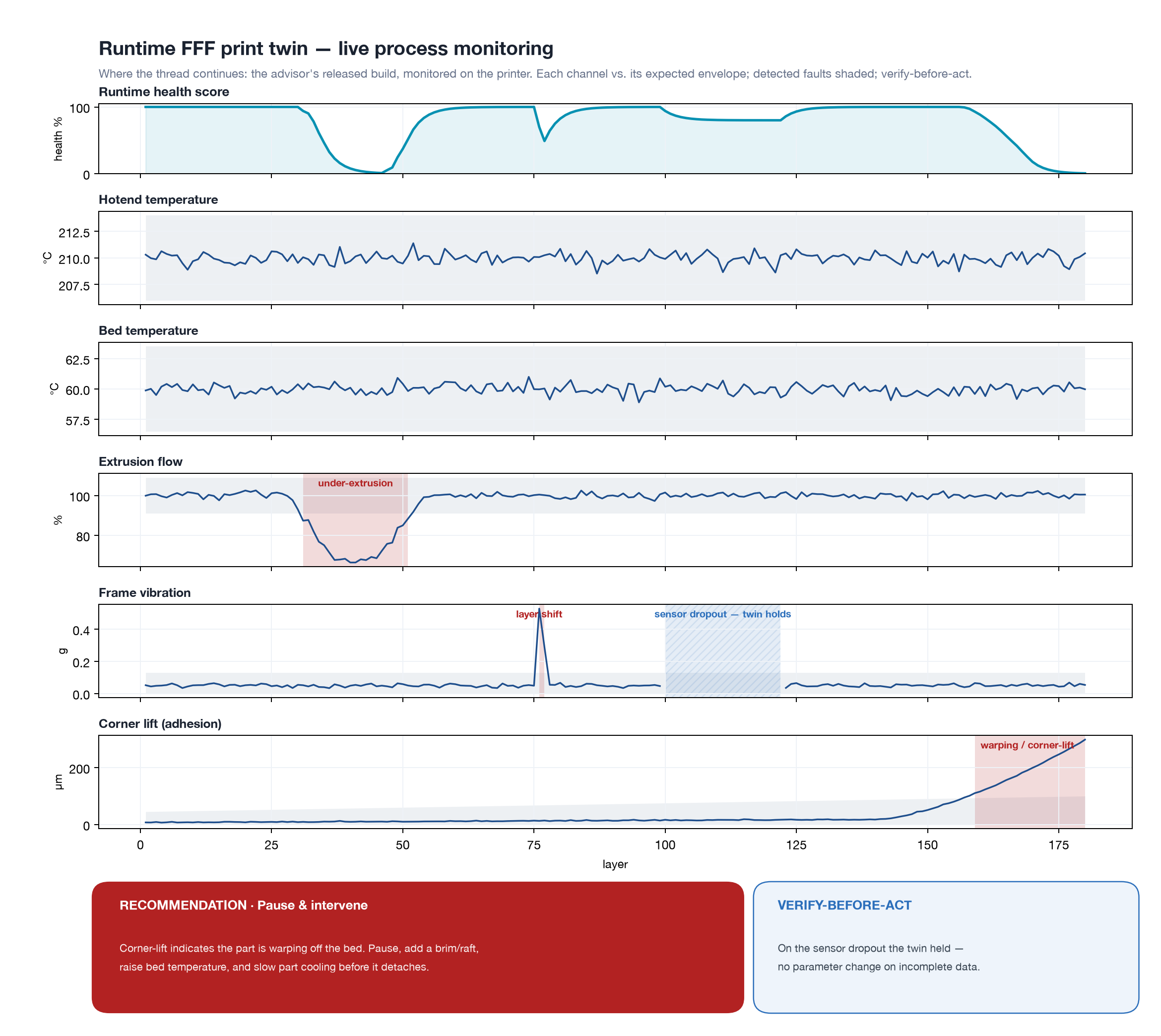
The advisor ends in a machine-readable release record, and that record is the hand-off point. Once the part is on the printer, a companion runtime FFF print-monitoring twin takes over: it synthesizes the sensor streams an instrumented machine produces — hotend and bed temperature, extrusion flow, frame vibration, and the corner-lift off the bed the FEA predicted — compares each against its expected envelope, flags deviation windows, tracks a smoothed health score, and recommends action. It carries the same verify-before-act discipline as the release gate: on a sensor dropout it refuses to recommend a parameter change rather than acting on incomplete data. Together the two halves span design → build → monitor.
Technical report
The full write-up — formulation, equations, validation, and limitations — is in the PDF report.